Hardware Descriptive Languages (HDLs)
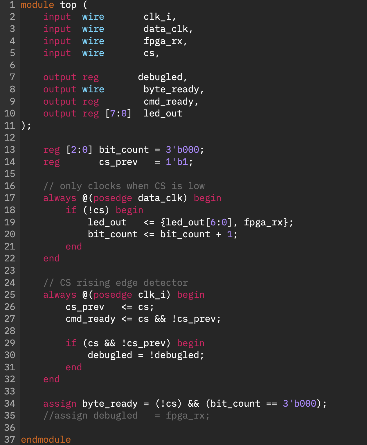
To configure the physical channels and logic blocks within an FPGA, engineers do not use traditional software programming languages like C++ or Python. Instead, they rely on Hardware Description Languages (HDLs). While software languages tell a CPU a sequence of actions to take over time, an HDL describes the literal structure and physical layout of electronic circuits operating simultaneously in space.
The Hardware Compilation Pipeline
Transforming text-based HDL code into functional hardware requires specialised vendor Integrated Development Environments (IDEs), such as Xilinx/AMD Vivado or Intel Quartus Prime. This compilation toolchain follows a rigid sequence of physical layout phases:
1. Synthesis & Netlist Generation
The compiler parses the text code and breaks down the behavioural logic into generic digital components (such as logic gates, multiplexers, and flip-flops). The output of this stage is a Netlist—a text database detailing every required logical component and the exact connections (nets) running between them.
2. Implementation: Placement & Routing
The IDE translates the abstract netlist into the actual physical geometry of the targeted silicon wafer:
- Placement: The software analyses the netlist and assigns specific logic equations to real, physical Look-Up Tables (LUTs) and Configurable Logic Blocks (CLBs) on the die.
- Routing: The tool determines the optimal configuration for the thousands of tiny switch matrices, establishing physical wire highways across the chip to join those blocks together without causing propagation signal delays.
[ Design Implementation Summary ]

  ┌────────────────┐      ┌────────────────┐      ┌────────────────┐
  │  HDL SOURCE    │ ───► │   SYNTHESIS    │ ───► │  GATE NETLIST  │
  │ (Logic Design) │      │ (Logic Mapping)│      │(Component Map) │
  └────────────────┘      └────────────────┘      └────────────────┘
                                                          |
                                                          ▼
  ┌────────────────┐      ┌────────────────┐      ┌────────────────┐
  │   BITSTREAM    │ ◄─── │    ROUTING     │ ◄─── │   PLACEMENT    │
  │ (.bit / .bin)  │      │(Physical Wires)│      │ (Silicon Sites)│
  └────────────────┘      └────────────────┘      └────────────────┘
What is a Bitstream?
00000000: d901 ed96 104d d600 0000 0033 0000 0000  .....M.....3....
00000010: dd01 8df1 80c4 42c1 18fc 4000 0000 0000  ......B...@.....
00000020: 0000 0000 0000 0000 0000 0010 0018 0000  ................
00000030: 0000 0063 b500 0000 0000 00c8 023f 2850  ...c.........?(P
00000040: 0e57 c6ca 66ad 3e00 0000 0000 0000 0000  .W..f.>.........
00000050: 0000 0000 0000 0000 0000 0000 0000 0000  ................
00000060: 0000 0000 0000 0000 0000 0000 0000 0000  ................
00000070: 0000 0000 0000 0000 0000 0000 0003 0000  ................
00000080: 0000 0000 0000 0000 0000 0000 0000 0000  ................
00000090: 0000 0000 0000 0000 0000 0000 0000 0000  ................
000000a0: 0000 0000 0000 0000 0000 0000 064d 4bc8  .............MK.
000000b0: 023f 2851 0e8f dfca 0530 6f02 0101 0001  .?(Q.....0o.....
000000c0: 16cd c802 3f28 5010 a83f ca66 ad3e 0000  ....?(P..?.f.>..
000000d0: 0000 0000 0000 0000 0000 0000 0000 0000  ................
000000e0: 0000 0000 0000 0000 0000 0000 0000 0000  ................
000000f0: 0000 0000 0000 0000 0000 0000 0000 0000  ................
00000100: 0000 0000 0000 0000 0300 0000 0000 0000  ................
00000110: 0000 0000 0000 0000 0000 0000 0000 0000  ................
00000120: 0000 0000 0000 0000 0000 0000 0000 0000  ................
00000130: 0000 0004 0937 c802 3f28 5110 7026 ca05  .....7..?(Q.p&..
00000140: 306f 0201 0100 0116 cdc8 023f 2827 11ed  0o.........?('..
00000150: 93ca 5191 7b00 0000 0000 0000 0000 0000  ..Q.{...........
00000160: 0000 0000 0000 0000 0000 0000 0000 0000  ................
00000170: 0000 0000 0000 0000 0000 0000 0000 0000  ................
00000180: 0000 0000 0000 0000 0000 0000 0000 0000  ................
00000190: 0000 0000 0000 0000 0000 0000 0000 0000  ................
000001a0: 0000 0000 0b50 c484 c802 3f28 2911 fd09  .....P....?()...
000001b0: ca50 186a 0000 0000 0000 0000 0000 0000  .P.j............
...
The ultimate objective of the toolchain is to generate a
Bitstream (typically a .bit or
.bin file). A bitstream is a dense stream of binary data
that contains no processor instructions or software application data.
Instead, it is a direct configuration map for the FPGA's underlying
internal memory cells.
Each bit in the file corresponds to a specific configuration point on the chip: turning a routing switch on or off, defining the truth-table rows inside an individual LUT, or setting up the electrical standard of an I/O pin. Loading a bitstream physically constructs the targeted hardware architecture inside the chip.
Hardware Deployment Methods
Because most standard FPGAs are based on volatile SRAM memory, they lose their custom configuration whenever power is disconnected. To boot up successfully, the chip must be programmed or loaded using one of several industry hardware interfaces:
| Protocol | Operational Mechanism | Primary Deployment Scenario |
|---|---|---|
| JTAG (Joint Test Action Group) | A 4-wire or 5-wire synchronous test bus that connects directly from the developer's computer via a USB probe straight into the FPGA's configuration registers. | Used extensively during desktop development, debugging, and real-time hardware signal tracing. Memory configuration is lost instantly on power down. |
| SPI (Serial Peripheral Interface) | A common 4-wire synchronous serial communication interface. Upon power-up, the FPGA acts as a master device and automatically fetches its configuration file. | Used in production environments. The bitstream is written to a permanent, non-volatile external flash memory chip sitting next to the FPGA on the PCB. |
| SWD (Serial Wire Debug) | A compact 2-wire alternative interface primarily optimised for microcontrollers and specific ARM-based SoC architectures. | Utilised on hybrid heterogeneous chips where an embedded processor core manages the boot and configuration state of the adjacent logic fabric. |
[ HIGH-RELIABILITY DEPLOYMENT TOPOOLOGY (SPI MODE) ]

 ┌────────────────────────┐                  ┌────────────────────────┐
 │   External Non-Volatile│  SPI Bus Lines   │   Volatile FPGA Die    │
 │     Flash Memory       │─────────────────►│ (SRAM Logic Framework) │
 │  [Holds Bitstream Map] │                  │ [Loads Map at Boot-up] │
 └────────────────────────┘                  └────────────────────────┘
The Core Languages
The global electronics community relies primarily on two major historical standardisations of HDL design, each with entirely contrasting syntax systems and engineering design philosophies:
Verilog HDL →
Based heavily on the style of the C programming language. Compact, highly flexible, and allows for rapid structural modifications, though its loose type-checking can introduce subtle physical bugs if not carefully written.
VHDL →
Derived directly from the Ada programming language. Incredibly strict, strongly typed, and highly verbose. Its design ensures that complex multi-million gate projects remain structurally sound and verify perfectly before synthesis.